Next: Display calibration Up: Calibration Previous: Calibration
If you have digitized your own signals, however, you should generally calibrate them before processing them further. WAVE makes it easy to do so, provided that you have recorded signals with known amplitudes. The procedure is:
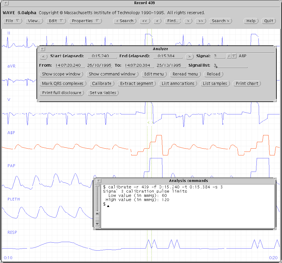 |
Figure 5.1 illustrates signal calibration using a record from the MIMIC Database. In this case, the type of signal (ABP) is known from an entry in the WFDBCAL file (not shown here), so that calsig is able to determine the physical units of the signal (mmHg). Since a variety of calibration pulses are used for ABP signals, the WFDBCAL file does not specify the pulse levels, which calsig has asked us to enter (in this case, we have entered 60 and 120). Based on this information, calsig determines the offset and gain needed to convert raw sample values for signal 3 into ABP measurements in mmHg. calsig then makes the appropriate changes to the header file for the current record. When WAVE or another WFDB application next opens this record, the ABP signal will be properly calibrated.
By default, calsig generates an amplitude histogram of the samples between the `<' and `>' markers. It then identifies the low and high amplitude portions of the calibration pulse by searching for the two largest distinct modes in this amplitude histogram. For this reason, calsig works best if the segment bounded by the `<' and `>' markers includes at least a few samples of both the high and low amplitude phases. Avoid placing either marker immediately next to the transition point between the phases if possible. If calsig fails to find two distinct peaks in the amplitude histogram, it will produce an error message; if this happens, adjust the positions of the markers and try again.
In some cases (for example, if the calibration pulse is a sawtooth, as in the RESP signal at the bottom of figure 5.1), this strategy may fail, no matter where the markers are placed. In such cases, try again with calsig's -q or -Q options to use one of its alternate algorithms. (These are less robust since they depend on differential rather than integrative measurements, but they can be used in a pinch.)
For further information on signal calibration, see calsig(1), in the WFDB Applications Guide.
George B. Moody (george@mit.edu)